Checkpoint 6: Learn
to run a motor using PWM and an H-Bridge.
Goals for this Checkpoint:
-
Learn how to attach headers to a chip.
-
Learn what an HBridge does and how
to use it.
The following materials were
adapted from http://bildr.org/2012/04/tb6612fng-arduino/.
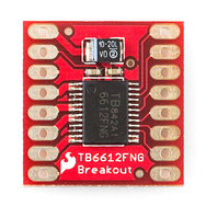
Step 1: Prepare the HBridge. You will need to solder headers onto the HBridge.
 Normally,
you solder the headers on so that when you plug them into the board, the chip
points upward allowing for the best seating of the HBridge
into your breadboard. However, in this
case, we will get better results if we insert the header pins so that the chip
side is down and thus the pin labels will be visible when plugged into the
breadboard.
Normally,
you solder the headers on so that when you plug them into the board, the chip
points upward allowing for the best seating of the HBridge
into your breadboard. However, in this
case, we will get better results if we insert the header pins so that the chip
side is down and thus the pin labels will be visible when plugged into the
breadboard.
When soldering, it might be
easiest if you insert the headers into the breadboard and place the HBridge in the desired direction on the headers. This will allow for a nice stable soldering
platform.
There are several sites online
where you can gain some solder tips and watch soldering tutorial videos. One example is:
http://www.aaroncake.net/electronics/solder.htm
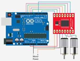 Step
2: Wire your Arduino up as shown.
Step
2: Wire your Arduino up as shown.
Note that “Motor Power +” in
the diagram goes to Vin on the Arduino.
Warning: There are a couple of combinations that you could make that
could damage or kill you Uno and/or your HBridge. It is always best to have a friend double
check your work before you plug anything in.
We will be using the TB6612FNG
dual H-bridge. An h-bridge is a
combination of transistors that allows you to switch the direction of current
running through your motor circuit. This
allows you to run a motor in both directions.
Using Pulsed Width Modulated (PWM) current, you can then make a motor
run at any speed. The TB6612 has 2
H-bridges allowing you to run two motors simultaneously.
The TB6612 can supply up to 13V
at 1.2A continuously.
To hook up the TB6612 we will
need an external power source somewhere in the range of 2.5V – 13V. We can’t use the 5V pin on the Arudino because it can’t provide enough current to run the
motors. WARNING: If you don’t hook this up correctly, you can
easily fry your Hbridge and/or your Arduino.
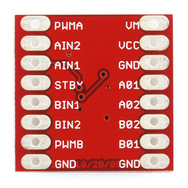
The “Standby” pin on the TB6612
when held LOW will turn off both motors.
Each motor then has 3 pins –
two of these are for direction the third one is for speed. When one direction pin is HIGH and the other
LOW then the motor will spin in one direction – switching the HIGH and LOW will
then switch the direction. The PWM pin
allows you to analogWrite
to the pin to control the speed of that one motors. Sending 0 to this pin stops the motor while
a 255 represents maximum speed.
Step 3: Upload new code to the Arduino.
//This
code controls two motors
//motor
A should be connected between A01 and A02
//motor
B should be connected between B01 and B02
//The
below code defines the output pins on the Arduino will hookup to specified pins
on the HBridge
int STBY =
10; //this will be the standby pin
//Motor
A
int PWMA =
3; //Speed control
int AIN1 =
9; //Direction
int AIN2 =
8; //Direction
//Motor
B
int PWMB =
5; //Speed control
int BIN1 =
11; //Direction
int BIN2 =
12; //Direction
void
setup(){
pinMode(STBY,
OUTPUT);
pinMode(PWMA,
OUTPUT);
pinMode(AIN1,
OUTPUT);
pinMode(AIN2,
OUTPUT);
pinMode(PWMB,
OUTPUT);
pinMode(BIN1,
OUTPUT);
pinMode(BIN2,
OUTPUT);
}
void
loop(){
move(1, 255, 1); //motor 1, full speed, left
move(2, 255, 1); //motor 2, full speed, left
delay(1000); //go for 1 second
stop(); //stop
delay(250); //hold for 250ms until move again
move(1, 128, 0); //motor 1, half speed, right
move(2, 128, 0); //motor 2, half speed, right
delay(1000); //go for another second
stop();
delay(250);
}
void
move(int motor, int speed, int direction){
//Move
specific motor at speed and direction
//motor:
0 for B 1 for A
//speed:
0 is off, and 255 is full speed
//direction:
0 clockwise, 1 counter-clockwise
digitalWrite(STBY,
HIGH); //disable standby
boolean inPin1 =
LOW;
boolean inPin2 =
HIGH;
if(direction == 1){
inPin1 = HIGH;
inPin2 = LOW;
}
if(motor == 1){
digitalWrite(AIN1,
inPin1);
digitalWrite(AIN2,
inPin2);
analogWrite(PWMA,
speed);
}else{
digitalWrite(BIN1,
inPin1);
digitalWrite(BIN2,
inPin2);
analogWrite(PWMB,
speed);
}
}
void
stop(){
//enable
standby
digitalWrite(STBY,
LOW);
}